Performance Analysis of Channel Estimation and Adaptive Equalization in Slow Fading Channel
Advisor: Prof. Dapeng Oliver Wu
|| Abstract || Introduction || Result || Download || Future Work || Useful Links ||
In our project, we first build up a wireless
communication simulator including Gray coding, modulation, different channel
models (AWGN, flat fading and frequency selective fading channels), channel
estimation, adaptive equalization, and demodulation. Next, we test the effect of
different channel models to the data and image in receiver with constellation
and BER (bit error rate) plots under QPSK modulation. For Image data source, we
also compare the received image quality to original image in different chan-nels.
At last, we give detail results and analyses of the per-formance improvement
with channel estimation and adap-tive equalization in slow Rayleigh fading
channel. For frequency selective fading channel, we use linear equaliza-tion
with both LMS (least mean squares) and RLS (Recur-sive Least Squares) algorithms
to compare the different improvements. We will see that in AWGN channel, the
image is degraded by random noise; in flat fading channel, the image is degraded
by random noise and block noise; in frequency selective fading channel, the
image is degraded by random noise, block noise, and ISI.
Mobile communications and wireless network have experienced massive growth and commercial success in the recent years. However, the radio channels in mobile radio systems are usually not amiable as the wired one. Unlike wired channels that are stationary and predictable, wireless channels are extremely random and time-variant. It is well known that the wireless multi-path channel causes an arbitrary time dispersion, attenuation, and phase shift, know as fading, in the received signal. Fading is caused by interference between two or more versions of the transmitted signal which arrive at the receiver at slightly different times.
There are many diversity techniques to
address fading issue, such as OFDM, MIMO, RAKE receiver and etc. However, it may
be still necessary to remove the amplitude and phase shift caused by the channel
if you want to apply linear modulation schemes, such as the ones used in WiMAX.
The function of channel estimation is to form an estimate of the amplitude and
phase shift caused by the wireless channel from the available pilot information.
Channel estimation methods may be divided into two classes: pilot-based
estimation and blind estimation. In our project, we will focus on pilot-based
channel estimation with training data. The equalization removes the effect of
the wireless channel and allows subsequent symbol demodulation. An adaptive
equalizer is a time-varying filter which must con-stantly be retuned. A number
of different algorithms can be employed for these modules. In our project, we
use LMS (least mean squares) and RLS (Recursive Least Squares).
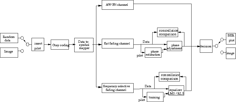
Figure 1 shows the flow chart of our model used in this project.
Figure 1: flow chart of Matlab simulation
Our simulation supports two kinds of source
data, either the randomly produced data or an image file. While random data is
ideal to test the channel impact to the BER performance and signal
constellation, image file give us an intuitive impression and comparison for
different channels.
After the source data is produced, the pilot data is inserted into head of
source data in each coherence time. It is used to estimate the random phase
shift of the fading channel and train the decision to adjust the received signal
with phase recover. User may set any percentage of the pilot data length to the
total data length (pilot data plus source data) in our model. In our simulation,
we set the pilot data as 8% of the total data length.
Then, user may choose to use gray coding or not in the simulation. After gray
coding, data is mapped from binary data to complex data, and each output datum
represents a point in the constellation diagram. In our model, we use phase
shift keying (PSK) modulation to modulate the data source, and user may choose
arbitrary M-ary PSK to modulate the signal. In our simulation, we test the QPSK
modulation.
In our simulation, we simulate three different channels: AWGN channel, Rayleigh
flat slow fading channel, and Rayleigh frequency selective slow fading channel.
AWGN channel is very straightforward by just add a white Gaussian noise into
signal to meet specified SNR. We simulate both flat fading and frequency
selective fading channels by Clarke and Gans fading model (Rappaport textbook).
User may set different velocity to get different coherence time for both these
two fading channels.
In the receiver side, we need channel estimation for flat fading channel or
adaptive equalizer for frequency selective fading channel. Since we use PSK
modulation in our model, the channel phase information in each coherence time
need to be estimated, and the weight of each tap in the equalizer need to be
trained by pilot data. Then, source data are adjusted by estimated phase for
flat fading channel or equalized by trained equalizer for frequency selective
fading channel. The received signal constellations of both with and without
adjustment are dynamically showed in the simulation. User may choose to plot
constellation or not in the program, and if they choose to plot constellation,
they may also set the SNR for the constellation.
Decision device decide each adjusted symbol, correspondent to each point in
constellation, to a binary datum. At last, we get the bit error rate by compare
source data and received binary data. For image data, the binary data is
converted back to image data and displayed.
All results are shown below:
Figure 2: Original Image
Figure 3: BER vs SNR (left) and received image (right) in AWGN channel.
Figure 4: Received image without channel estimation and adjustment (up-left), Received image with channel estimation and adjustment (up-right), BER vs SNR Result (down-left), and Constellation comparison (down-right) in Flat fading channel.
Figure 5: Received image without equalizaiton (up-left), Received image with equalizaiton (up-right), BER vs SNR Result (down-left), and Constellation comparison (down-right) in Ferquency selective fading channel.
Demo setup from youtube:
For more detail information, please refer to the course project paper.
download full files in winzip format here.
Source code:
Up to now, there are totally three versions of source code:
version 1.0 version 1.1 version1.2
Below codes come from version 1.2. Before run these codes, you may read the readme file here.
main: This is the main file, and user only need to run this file, which will call all the other files.
playdemo: this function is to set parameters for the program to run in play mode
image2data: this function is to transfer image to data suitable for transmission
MPSK_mod: M-PSK modulation
MyRayleigh: flat fading channel, generate Rayleigh fading with Clarke' Model
MyRayleighPDP: frequency selective fading channel, generate Rayleigh multipath fading with Clarke' Model
CE_flat: flat fading channel estimation In this program, I just estimate the average phase error and amplitude error
Constellation_flat: this function is to plot the constellation of received signal with and without phase estimation in the ith iteration, i.e. ith coherent time, where ith is random selected.
Constellation_FSF: this function is to plot the constellation of received signal with and without equalization, trained equalizer weights, and training curve in the ith iteration, i.e. ith coherent time, where ith is random selected.
MPSK_demod: M-PSK demodulation
data2image: this function is to transfer data type back to image for display
BER_AWGN: this function is to plot the BER of received signal
BER_flat: this function is to plot the BER of received signal with and without phase estimation
BER_FSF: this function is to plot the BER of received signal with and without equlization
Test files:
MPSK_AWGN_error: calculate and plot BER for M-PSK modulation in AWGN channel with exact phase information and phase estimation error
MPSK_flat_error: calculate and plot BER for M-PSK modulation in flat fading channel with exact phase information and phase estimation error
Documents:
Project paper: This is our course project paper. This will give you more idea on our project and details on what we have done
Presentation: Introduction and main topics
Project Proposal: This is a proposal before we begin this project. The final project paper is different from it by revise, add and remove some contents based on the further evaluation during development.
Figure 6 shows the flow chart of our model used in the next project.
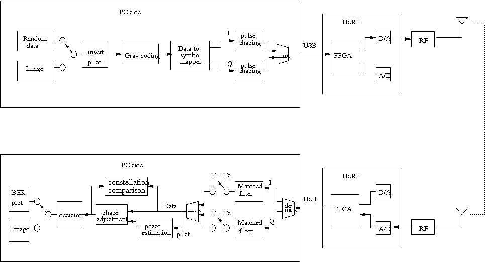
Figure 6: flow chart of future project
Our simulation supports two kinds of source data, either the randomly produced data or an image file. While random data is ideal to test the channel impact to the BER performance and signal constellation, image file give us an intuitive impression and comparison for different channels.
After the source data is produced, the pilot data is inserted into head of source data in each coherence time. It is used to estimate the random phase shift of the fading channel and train the decision to adjust the received signal with phase recover. User may set any percentage of the pilot data length to the total data length (pilot data plus source data) in our model. In our simulation, we set the pilot data as 8% of the total data length.
Then, user may choose to use gray coding or not in the simulation. After gray coding, data is mapped from binary data to complex data, and each output datum represents a point in the constellation diagram. In our model, we use phase shift keying (PSK) modulation to modulate the data source, and user may choose arbitrary M-ary PSK to modulate the signal. In our simulation, we test the QPSK modulation.
The output complex data is divided into In-phase and Quadrature (I/Q) branches. Each of them passes through a pulse shaping and then mix together to get filtered baseband signals. The last step in the PC side is to send the baseband signals to the USB interface, which are connected with an Universal Software Radio Peripheral (USRP) board.
In USRP board, FPGA interpolate the baseband signals, and D/A converter convert the digital signals into analog signals. At last, the output signals of USRP board is modulated by a RF module with specified carrier frequency, and transmitted.
In the receiver side, both RF module and USRP perform the reversed roles as their transmitter counterparts. The received digital signals are filtered by matched filters and sampled at sampling time in I/Q branches respectively. In an indoor environment, the wireless channel between two USRP boards is mostly like a flat fading channel. So, we need channel estimation to estimate the channel information and source data are adjusted by estimated phase. The received signal constellations of both with and without adjustment are dynamically showed in the simulation. User may choose to plot constellation or not in the program, and if they choose to plot constellation, they may also set the SNR for the constellation.
Decision device decide each adjusted symbol, correspondent to each point in constellation, to a binary datum. At last, we get the bit error rate by compare source data and received binary data. For image data, the binary data is converted back to image data and displayed.
Wireless Communication Project (EE381K-11) Technical Report
Optimal Channel Estimation for Capacity Maximization in OFDM Systems
http://users.ece.utexas.edu/~wireless/EE381K11_Spring03/projects/7.3.pdf
Channel Estimation Modeling:
http://www.comlab.hut.fi/opetus/260/chan_est.pdf
Adaptive Equalization of the Slow Fading Channel
http://ieeexplore.ieee.org/xpls/abs_all.jsp?arnumber=1092338
Probability of Decoding Error for Random Phase and Rayleigh Fading Channels
http://ieeexplore.ieee.org/iel5/18/22625/01053736.pdf?arnumber=1053736
MATLAB Central > File Exchange > Communications
http://www.mathworks.com/matlabcentral/fileexchange/loadCategory.do?objectType=category&objectId=1